m 5.0e and 25vf016b bios chip
hi guys
im hoping you can help me here
im trying to id this chip and program it
but cannot do it in any socket
i have the chip out
and 2 spare new ones
25vf016b
when i select it in the software (0.98-d11) it says vcc - 3.3 which ive opened the jumper for this
and it also says on the software to use the ICSP part of the programmer
question is im not sure what pins go where on the chip ???!!?
PGD,PGC ?!?! the chip as SI and SO im confused lol
my programmer has a SPI headder too
can i not wire it up to this ?
if any1 can point me in the right directions with jumper settings and pin wire ups
id greatly apreciate it
thanks
dave
Re: m 5.0e and 25vf016b bios chip
Place chip in 25xxx socket. For SOIC-8 apply SO8/DIP8 adapter.
Re: willem 5.0e and 25vf016b bios chip
hi ezo
thanks for the speedy reply
i have tried it in the 25Cxx socket, it will not identify the chip correctly
any other ideas on jumpers etc
as i had it setup for PLC32
thanks
dave
thanks for the speedy reply
i have tried it in the 25Cxx socket, it will not identify the chip correctly
any other ideas on jumpers etc
as i had it setup for PLC32
thanks
dave
Re: m 5.0e and 25vf016b bios chip
hi dave i have the same problem
i cant read write or do anything with tis chip
the support on the chip and explaning how to use read , write it is kinda bad
please please explane this sst25vf016b ( laptop bios )
thanks
WideOn
i cant read write or do anything with tis chip
the support on the chip and explaning how to use read , write it is kinda bad
please please explane this sst25vf016b ( laptop bios )
thanks
WideOn
Re: m 5.0e and 25vf016b bios chip
hi wideon
im hoping ezo can come back n help us with setup of my willem 5.0E board.
he came thru with flying colors on an other chip i had problems with
EZO..
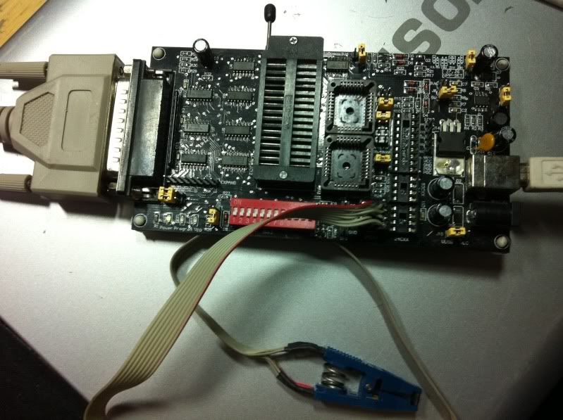
i have a 8 pin soich clip to 8 pin dil socket, which i pulged directly into the 25cxx port of the willem.
it will not id the chip at all
may b down to jumper settings and or dip switch settings
i have them all switched off by the way
thanks
dave
Re: m 5.0e and 25vf016b bios chip
What SW do you apply ? Have you tried 0.98d12c3 ?
I have tested chip on ezoflash4v5 only.
Generally Willem serial interface is compatible, here can be specifics like voltage levels on SPI inputs.
I will try on pcb5.0e and come back with results.
I ask you check voltages in Test H/W mode.
Activate 32-Vcc, measure voltage on 25xxx pins 8, 7, 3
Measure voltage on pin 5, activate 13-D0, voltage.
Activate 22-CE, measure voltage pin 1
Activate 14-D1, measure voltage pin 6
Re: m 5.0e and 25vf016b bios chip
well im still way over my head 
i need a lamers info on this chip where a put the chip in the 25f port or the icsp
i dont even understand even where to put the chip
please so a lamer info on the chip
thanks ezo and dave
i need a lamers info on this chip where a put the chip in the 25f port or the icsp
i dont even understand even where to put the chip
please so a lamer info on the chip
thanks ezo and dave
Re: m 5.0e and 25vf016b bios chip
im not sure what you mean in testing ezo
thanks
thanks
Re: m 5.0e and 25vf016b bios chip
ok in test h/w i ticked Vcc-32
then tested pins on 25cxx socket as follows
pin 8 = 3.79v
pin 7 = 3.79v
pin 3 = 3.79v
so all three pins the same there
13-DO activated..
pin 5 = 4.83v
22-CE activated..
pin 1 = 4.41v
14-D1 activated..
pin 6 = 1.18v
these are the tests mate
let me know if they are correct or not
thanks
PS tested teh chip in the port again and no go.
still not id'ing the chip
dave
Re: m 5.0e and 25vf016b bios chip
Are you able to find Test H/W section in SW ?
You are able activate any signal and usually measure voltage on ZIF32 related pin.
My idea to confirm signals and voltages directly on 25xxx DIP-8 socket pins.
---------------------
I made experiments on my pcb50e.
Test H/W results on 25xxx pins 8,7,3 - 3.66V (tick 32-Vcc) ; 5,1 (tick 22-CE),6 (tick 14-D1)- 4.72V. This is worsest input voltage compatibility found on willem designs. Usually programmer logic is powered at level ~4.3V (from 7805 through diod 1N4001). In pcb5e schotky 1N5819 applied (diod marked in picture between caps and 24Cxx socket), which reduce voltage ~0.3V.
Related problem could be - from datasheet SST25VF016B operating voltage range Vdd 2.7-3.6V, and any input allow overvoltage Vdd+0.5V (or Vdd+2.0 for very short <20ns transient process).
My pcb50e programmer SPI inputs overvoltage is 1.06V.
You can reduce difference - replace 1N5819 with 1N4007 (input voltages will drop down to ~4.3V), or place serial both diods 1N5819 and 1N4007 (input voltages will drop down to ~4.0V.
That's theory and practical look.
Some SPI chips allow more voltage and 4.3 is acceptable level. Unfortunately I do not have confirmation of input overvoltage impact (non-reliable chip answer, cause of damage, etc. )
-----------------
Regardless of above mentioned and without mods my pcb50e accept SST25VF016B. ID OK 0.98d11 (selected SST25VF016) and with 0.98d12c3 (autoselect). Test file programming OK. Power supply and jumper changed to USB - ID OK. Other chip SST25VF080B ID return OK.
Only removed jumper Open 3.6 (marked in picture) important for SPI flashes (suppose 5V jumper set as default).
Unfortunately no ideas more. Zip file with pictures and screenshots attached.
Adapter so8a1 used from ezoflash4v5, header sockets applied to fit in DIP8 socket .
- Вложения
-
- 50e_spi.zip
- (181.81КБ)453 скачивания
Re: m 5.0e and 25vf016b bios chip
Keep tick 32-Vcc activ for voltage measures on pins 1,5,613-DO activated..
pin 5 = 4.83v
Here pin 5 should have voltage when 13-D0 disabled.
When tick 13-D0 voltage drops down to 0V. Is it ?
Something wrong. Voltage schould be >4V or ~0V.14-D1 activated..
pin 6 = 1.18v
14-D1 activ (with OE-24 and 32-Vcc)-measure voltages on 4503/4 and 5 (top chip 4503, closest to 4069), ZIF32/14, 93Cxx/2, 24Cxxx/6, 25Cxx/6
Activate/deactivate 14-D1 to confirm voltage changes on listed pins.
Re: m 5.0e and 25vf016b bios chip
thanks ezo
i have some SPANSION 25FL016A
this chip auto detects fine
i just cannot get the SST to detect
my chip and clip adapter must be fine for it to pick up the SPANSION chip
these 2 chips are both 16mb yes ?
you think i could flash his bios dump to my SPASION and that would work in the laptop ?
not sure what i could try now
dave
Re: m 5.0e and 25vf016b bios chip
When tick 13-D0 voltage drops down to 0V. Is it ? <-----YES DROPS TO 0V
this is a pic of my board. its diff to your v5.0

dave
this is a pic of my board. its diff to your v5.0

dave
Re: m 5.0e and 25vf016b bios chip
I suppose one of 4503 is equal to non-smd design.14-D1 activated..
pin 6 = 1.18v
Something wrong. Voltage schould be >4V or ~0V.
14-D1 activ (with OE-24 and 32-Vcc)-measure voltages on 4503/4 and 5 (top chip 4503, closest to 4069), ZIF32/14, 93Cxx/2, 24Cxxx/6, 25Cxx/6
Activate/deactivate 14-D1 to confirm voltage changes on listed pins.
Try listed measures.
Both chips are 16Mb S25FL016 and SST25VF016B. Not sure in compatibility, depends from PC.these 2 chips are both 16mb yes ?
you think i could flash his bios dump to my SPASION and that would work in the laptop ?
long cable from chip to programmer may affect reliable functionalitythis is a pic of my board. its diff to your v5.0
Re: m 5.0e and 25vf016b bios chip
thanks for the reply
ive tried the chip pretty much directly soldered to the socket.
same results
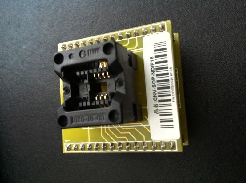
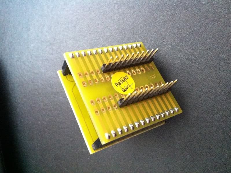
i do however have a smd 8 pin adapter here
not sure if it will work in the willem tho.
can you advise ?
do you know what pins of the zip socket correspont to pin numbers of the chip when in teh programming mode for said chip ?

**************************************************************

what do you think
will this work
but as i said it depends on teh pin configurations of the willem
i dont mind cutting tracks on this adapter as i never used it b4 so may as well get some use
dave
ive tried the chip pretty much directly soldered to the socket.
same results
i do however have a smd 8 pin adapter here
not sure if it will work in the willem tho.
can you advise ?
do you know what pins of the zip socket correspont to pin numbers of the chip when in teh programming mode for said chip ?

**************************************************************

what do you think
will this work
but as i said it depends on teh pin configurations of the willem
i dont mind cutting tracks on this adapter as i never used it b4 so may as well get some use
dave
