                   How to use the epromprogrammer version 3.0, 3.1, 3.1 ATH, 4.0, 4.5.
				   update 15-10-2005
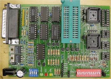 Board 4.0
The 3 pole normal/29X040 header is now called Vpp/A18,19.
Standard setting: Vpp, for 29F040,29C040 and for the 27C080(801) A18,19.
The SF erase header is now 3 pole and has 2 positions : normal and erase.
Standard setting is normal.
For DIP 24 chips there are 2 new headers Normal/DIP 24 and Vpp/A11.
Standard setting is normal and A11.
For DIP 24 chips set jumpers to: from Normal to DIP 24, 2732 -> A11, 2716 -> Vpp.
For the HUB/Firmware socket there is one Vpp header.
Standard settings open, closed for Intel 82802 chips
To set Vcc and Vpp there is a 4 way DIP switch:
1 and 2 are for Vpp: 1 ON Vpp=21 volt , 2 ON Vpp= 12.6 volt
standard setting 1 OFF, 2 ON Vpp=12.6 volt.
updated resistor values
3 and 4 are for Vcc: 3 ON Vcc=5 volt, 4 ON Vcc= 3.3 volt, 3 OFF and
4 OFF Vcc=6.0 volt.Standard setting 3 ON and 4 OFF Vcc=5.0 volt.
Vpp and Vcc voltages can be modified easy with different resistor values.
For low voltage flash devices the 3.3 volt setting can be used,
in that case voltage drop diodes on adapters must not be used of course.
On the tsop 48 adapter short the 5 volt jumper.
For the Firmware/HUB adapter set to 5 volt.Sometimes it's necessary to increase R/C delay time:
set it higher until the chip ID is correct.
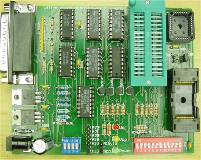
                   Board 4.0
                   The 3 pole normal/29X040 header is now called Vpp/A18,19.
                   Standard setting: Vpp, for 29F040,29C040 and for the 27C080(801) A18,19.

                   The SF erase header is now 3 pole and has 2 positions : normal and erase.
                   Standard setting is normal.

                   For DIP 24 chips there are 2 new headers Normal/DIP 24 and Vpp/A11.
                   Standard setting is normal and A11.
                   For DIP 24 chips set jumpers to: from Normal to DIP 24, 2732 -> A11, 2716 -> Vpp.

                   For the HUB/Firmware socket there is one Vpp header.
                   Standard settings open, closed for Intel 82802 chips

                   To set Vcc and Vpp there is a 4 way DIP switch:
                   1 and 2 are for Vpp: 1 ON Vpp=21 volt , 2 ON Vpp= 12.6 volt
                   standard setting 1 OFF, 2 ON Vpp=12.6 volt.
                    updated resistor values

                   3 and 4 are for Vcc: 3 ON Vcc=5 volt, 4 ON Vcc= 3.3 volt, 3 OFF and
                   4 OFF Vcc=6.0 volt.Standard setting 3 ON and 4 OFF Vcc=5.0 volt.
                   Vpp and Vcc voltages can be modified easy with different resistor values.

                   For low voltage flash devices the 3.3 volt setting can be used,
                   in that case voltage drop diodes on adapters must not be used of course.
                   On the tsop 48 adapter short the 5 volt jumper.

                   For the Firmware/HUB adapter set to 5 volt.Sometimes it's necessary to increase R/C delay time:
                   set it higher until the chip ID is correct.
The ICSP connector is for external PIC chips programming.
                   Board 4.5 has no SF erase option and no support for serial eeproms and Microchip PIC's.
                   To use the TSOP 48 ZIF see tsop page, you don't need to connect the higher address lines
                   of course.You can choose between 5 different Vcc voltages, this depends on the chip you
                   are using, check a datasheet if in doubt.
                   For LV(low voltage)chips 3.3 will be ok.
                   4-way dipswitch setting: 1 ON 2.7, 2 ON 3.0, 3 ON 3.3, 4 ON 5.0, all OFF 6.0 volt.
                   Vcc voltages can be modified easy with different resistor values.
                    updated resistor values

                   Board 3.0/3.1, 3.1 ATH, 4.0 and 4.5.
                   Set the jumpers to A18 and normal(on boards 4.0/4.5 called Vpp) for standard use.
                   Set the jumper to A19 for XXX080 devices.
                   Set the jumper to 29X040(on boards 4.0/4.5 called A18,19)for the 29F040,29C040 and for the 27C080(801)
                   A19,A20,A21 are used to connect to the TSOP 48 adapter.
                   For connection details see the tsop page .
A19,A20,A21 are also used to connect to the 16 bit 42 pin adapter(27C400..27C322).
For connection details see the 16 bit combi adapter page.
                   Close the 27SF erase jumper only to erase SST27SFXXX devices.

                   The power supply can be a standard "12 Volt adapter" 300-500 mA unstabilised that gives about
                   16 volt.This is not critical output voltage can be between 15 and 20 volt.

                   The two DIP switch should be both ON,you can select Vpp 21 volt if the 8.2 Zener diode is mounted:
OFF ON. Supply voltage must be 24 Volt min. for 21 Volt operation. 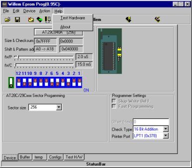
                   Check the printerport setting in the BIOS,it should be EPP or Normal
                   Also check or there are resident programs active that use the printerport,like
                   TWAIN drivers.You may have to remove them.

                   XP can also give problems when you connect your programmer see XP polling problem
                   It's highly recommended to do this registry update if you use XP,
                   Eprom's can be changed(written to) during a read or verify.

                   Connect to the printer port with a 25 SubD cable,the cable should not be longer
                   than 1.8 meter(6 feet standard cable).
                   This must be a fully wired 1:1 cable,a null modem or serial cable won't work.
                   Connect the power supply,the power led must go on.
Make sure that the PORTIO drivers are in the same directory as the main program.
Some driver problems may occur under Windows 2000:
                   * first,  delete an entry in the device manager as follows:
                   1.  On the Start Menu, click Start --> Settings --> Control Panel.
                   2.  In the Control Panel, double click the System icon.
                   3.  In the System Properties window, click the Hardware tab.
                   4.  On the Hardware tab, click the Device Manager button.
                   5.  In the Device Manager menu, click View --> Show Hidden Devices.
                   6.  In the device list find the Non-Plug and Play Drivers entry. Click the 'plus'
                   sign on the left of the entry to expand the list.
                   7.  Find the dlportio entry and right-click it. Click on Uninstall in the context menu that appears.

                   If it is not there already, then no problem carry on.

                   * in the registry, I deleted entries that had to do with dlportio.
                   search for dlportio and delete any folder that refers to it.
                   I think this just removes any OS reference to dlportio, so like you are starting fresh.

                   * download TLDPortIO from the web

                   * install the drivers using the utility--play around with it a bit--the point is
                   to get the DLL and SYS file installed in the system and start a service.

                   * notice that with the driver files installed, and the driver files
                   in the director that willem97g is in had better be the same.....and that
                   the burner software still requires the DLL and SYS file in the same directory
                   Thanks to sadolph.
Test the connection with TestHardware
In the program set to 'Willem' (only needed with first use)
Not needed for the 3.1ATH or 4.0/4.5 boards.(the 'Willem' setting only changes
the DIPswitchsetting picture)
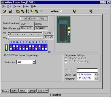
Select device type and set the DIPswitch .
DIPswitch switches can be red(like in the sofware),white or other colors.
Insert chip and check ID.(not possible with older 27(C)XXXX devices)
If you can't get a valid chip ID it's useless to try reading,erasing or writing.
A valid ID gives the right manufacturer and chip type
Erase if necessary,load program file and program,the Vcc led
will light and with 27,28 devices the Vpp led also.
Warning: never insert an eprom when you haven't started the program yet
and the Vpp and Vcc leds are still burning.
Never remove the power supply lead or disconnect the adapter when an
eprom is still in the socket, also make sure the power lead is firmly
connected to the board and can't become disconnected.
All of this can cause random "writes" to your eprom and change it's contents.
Programming can fail in different ways:
First byte,error message: error at 0x000000 Buffer=0xXX ,Chip=0xFF or 0xXX.
Causes: chip not inserted right,faulty chip, Vpp too low, Vcc too low or Vcc too high.
random error,error message: error at 0xXXXXXX ,Buffer=0xXX ,Chip=0xXX
Causes: 27CXXX eprom not completely UV erased,tWP/tWC too low,other causes. Normally you should not change tWP and tWC unless you know what you are doing.
If you get random write errors with 27(C)XXX eproms try higher settings.
Most older NMOS eproms like the 2716 need higher settings. In the Buffer section you can see the contents of your program file or the chip
if you have done a chip read. The configs section give an overview of all settings and parameters.
                   If you need PIC in circuit programming,
                   you can use a DIP connector for the 18 pin PIC 16F84 socket(5 gnd.,12 clock,13 data i/o,14 Vcc).
The Test H/W section is for testing purposes,see the debug hardware page.